Visualizing and editing fluid level surfaces
Fluid level surfaces are created when fluid level data (i.e. GOC, FWL) is entered and applied on the Fluid Levels form. They are stored in the JewelExplorer in their corresponding fluid compartment folder (Fluid Models > Your Fluid Model > Fluid Compartments > Your Compartment).
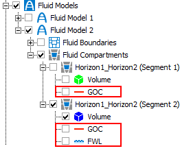
Fluid models are stored in the Jewel Explorer. Fluid level surfaces are placed in their corresponding fluid compartment folder. click to enlarge
You can display your fluid level surfaces in a 3D View or Well View for QC purposes. In this way you can ensure that your fluid model honors the well data.
 .
.
- Open a 3D view (Workspace > Views > 3D View).
- In the JewelExplorer, check the box for each of the fluid level surfaces you want to visualize, along with any other data.
-
You can control the display settings of the fluid level surfaces via the context menu options.
Display settings
Extend Fluid Level The fluid level surface intersecting the compartment volume is displayed in the color of the GOC or FWL, whereas the extended area is displayed in gray color.
Select this option to extend your fluid level surface to the model area boundaries.
Deselect this option to keep your fluid level surface bound by the compartment boundaries.
Transparency Select this option to make the fluid level surface transparent, to better observe the model. You can change the transparency level via the Property Inspector.
- You can observe the fluid level surfaces and their placement with other fluid compartment data, and make adjustments if necessary.
- Open a Well View (Workspace > Views > Well View).
- In the Jewel Explorer, check the boxes for each of the wells, logs and fluid level surfaces you want to display. The fluid level surfaces appear in the Well View as dashed lines; blue dashed lines represent FWL surfaces, while red dashed lines represent GOC surfaces. You can change the color of the fluid level surfaces via the Property Inspector .
- You can observe how the fluid level surfaces match up with the well data, and make adjustments if necessary.
Instead of editing the values on the Fluid Levels form, you can use the Editing Tools for the Well View to adjust the depths of the fluid level surfaces.
- Open the Editing Tools from the Tools menu in the top-right corner of the application (Workspace > Tools > Editing Tools or Shift+F1). The Editing Tools floating palette displays all the tools available for use in the Well View.
- Select the Move Fluid Level tool
 .
. - Hover over the fluid level surface in the track where you want to make the adjustment. Click and drag the fluid level surface to the desired depth. The values on the Fluid Levels form are updated automatically.